Pt. 1: Making A Custom Sport Classic Seat
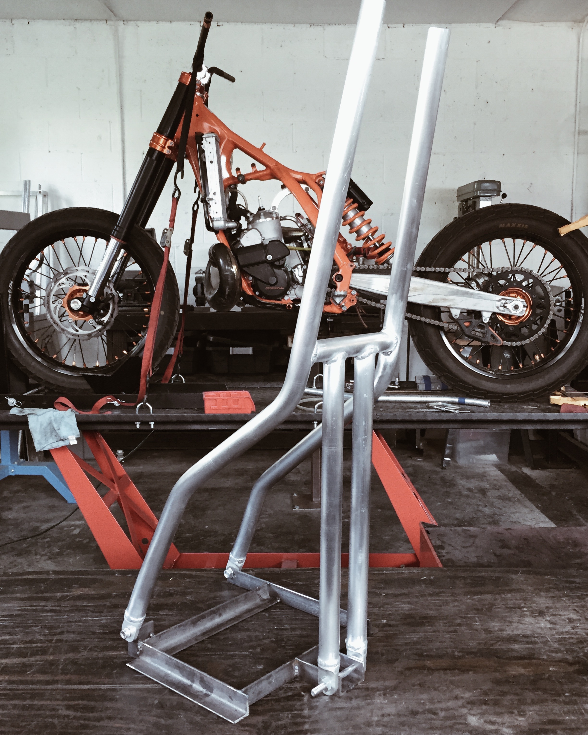
A client came to me recently with a 2016 Ducati SC100 looking to transform it's appearance on a tight budget. In my opinion, one of the best bang-for-the-buck transformation pieces is a custom seat. We decided to look at redesigning what was on there while retaining subframe mounts and tabs so that the bike could be brought back to stock relatively easy. I'll go through my entire process over a few blog posts to help anyone else trying to tackle something similar.

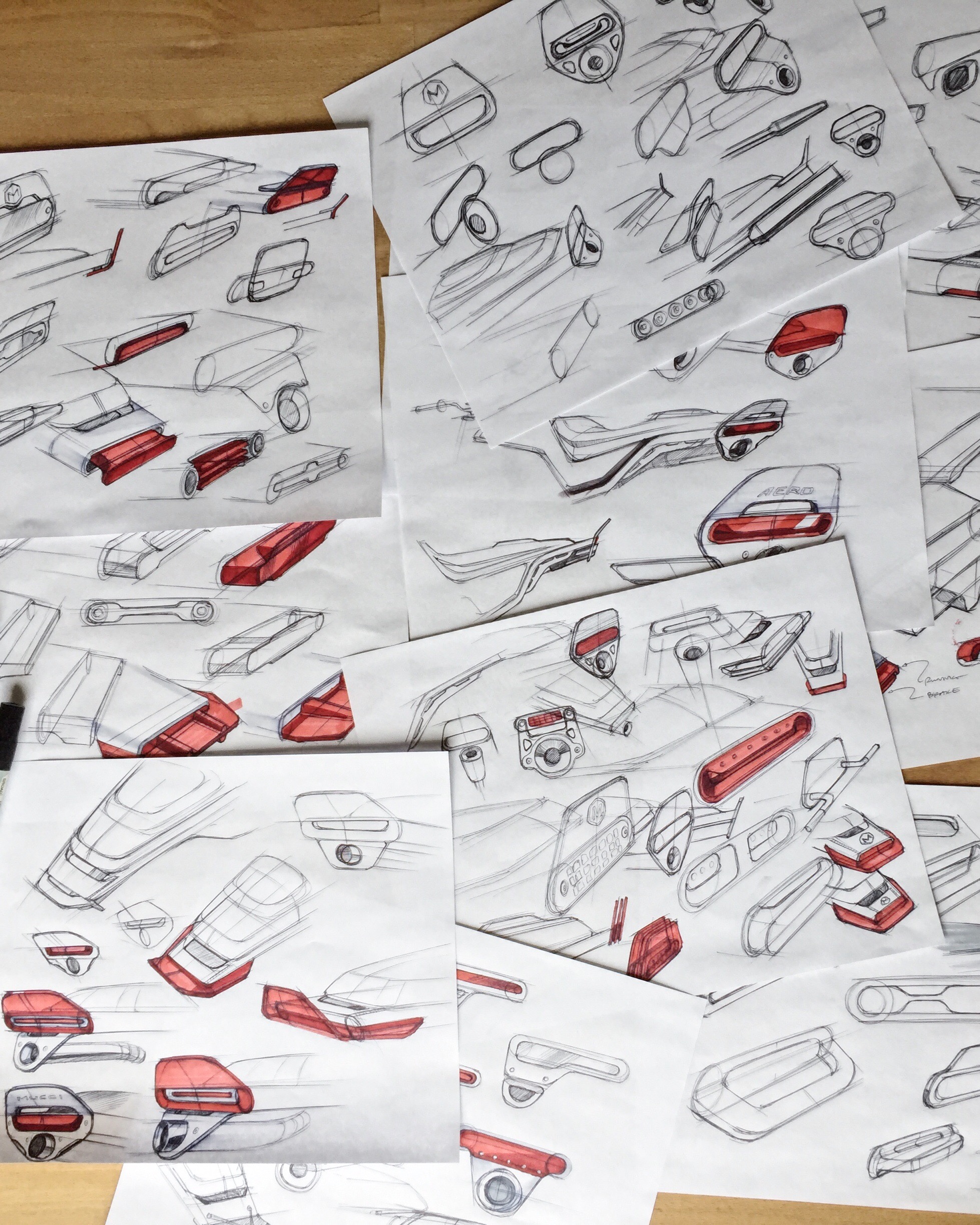
As with all my custom work, it started out in 2D. I like to create a design plan before touching a bike. I find it helps make execution much more straight forward. Here were the different iterations we discussed. 

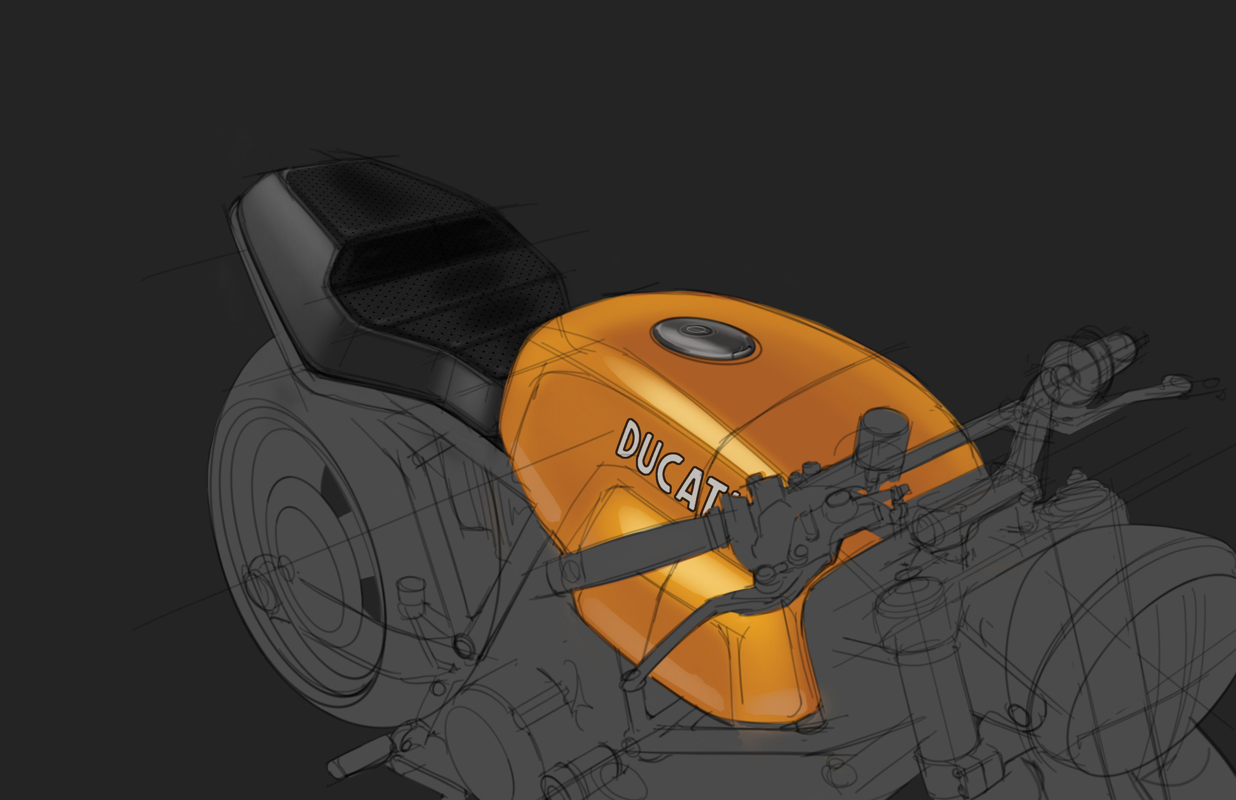
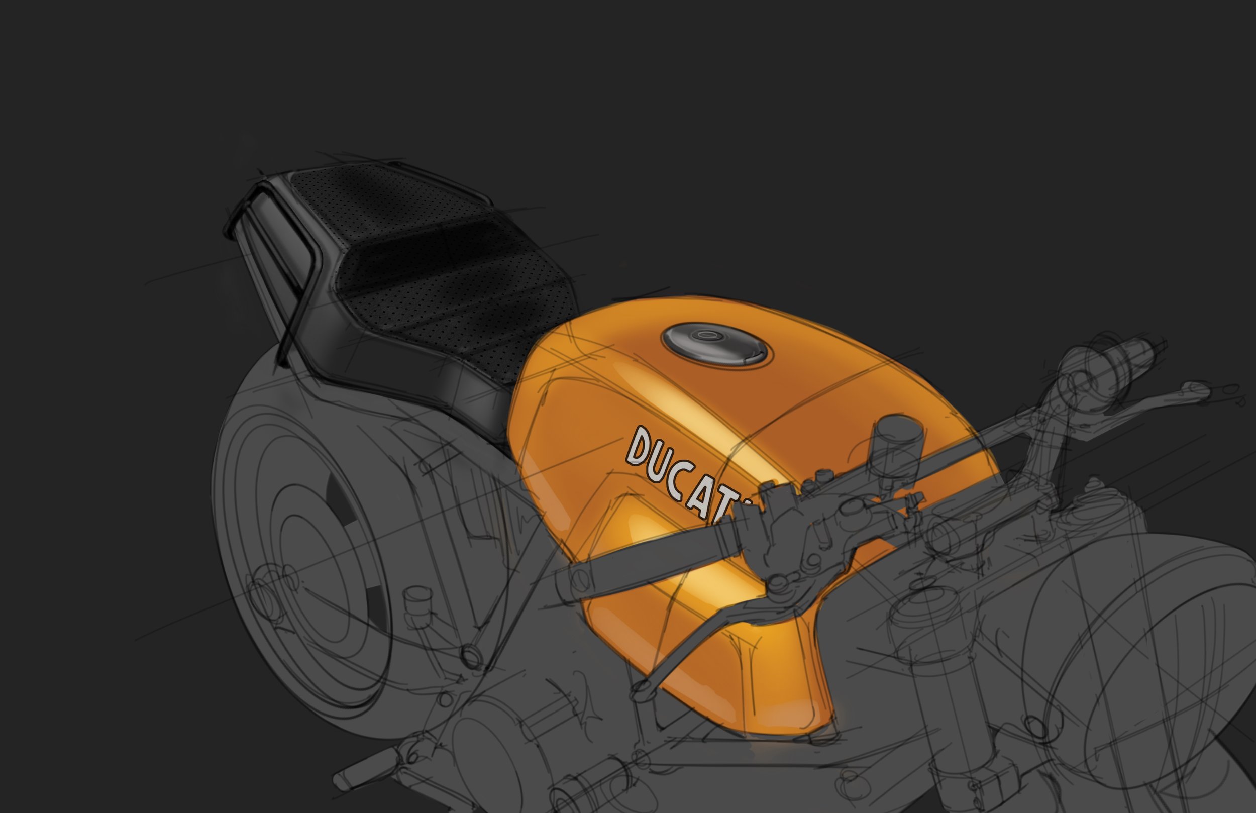
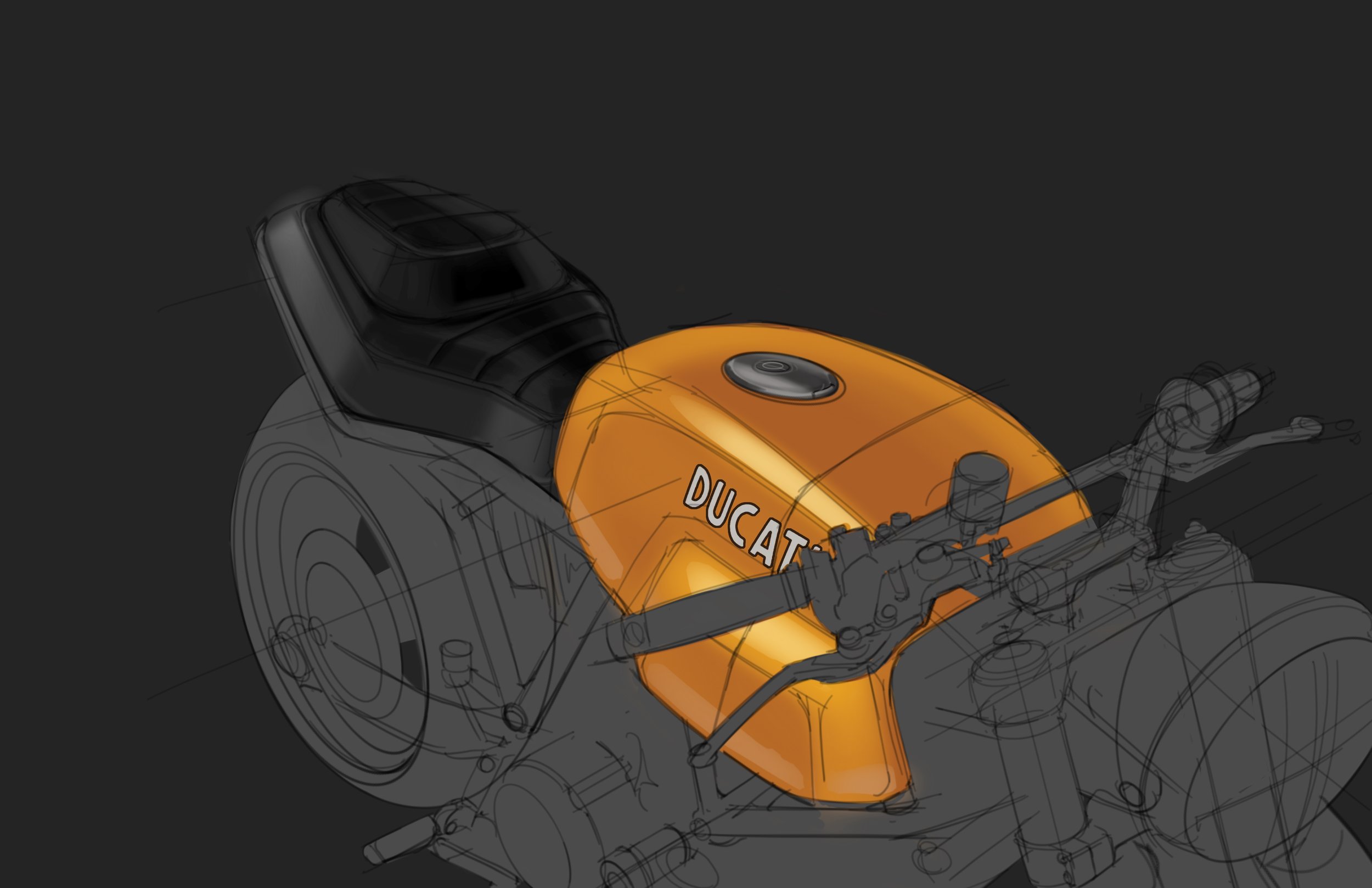
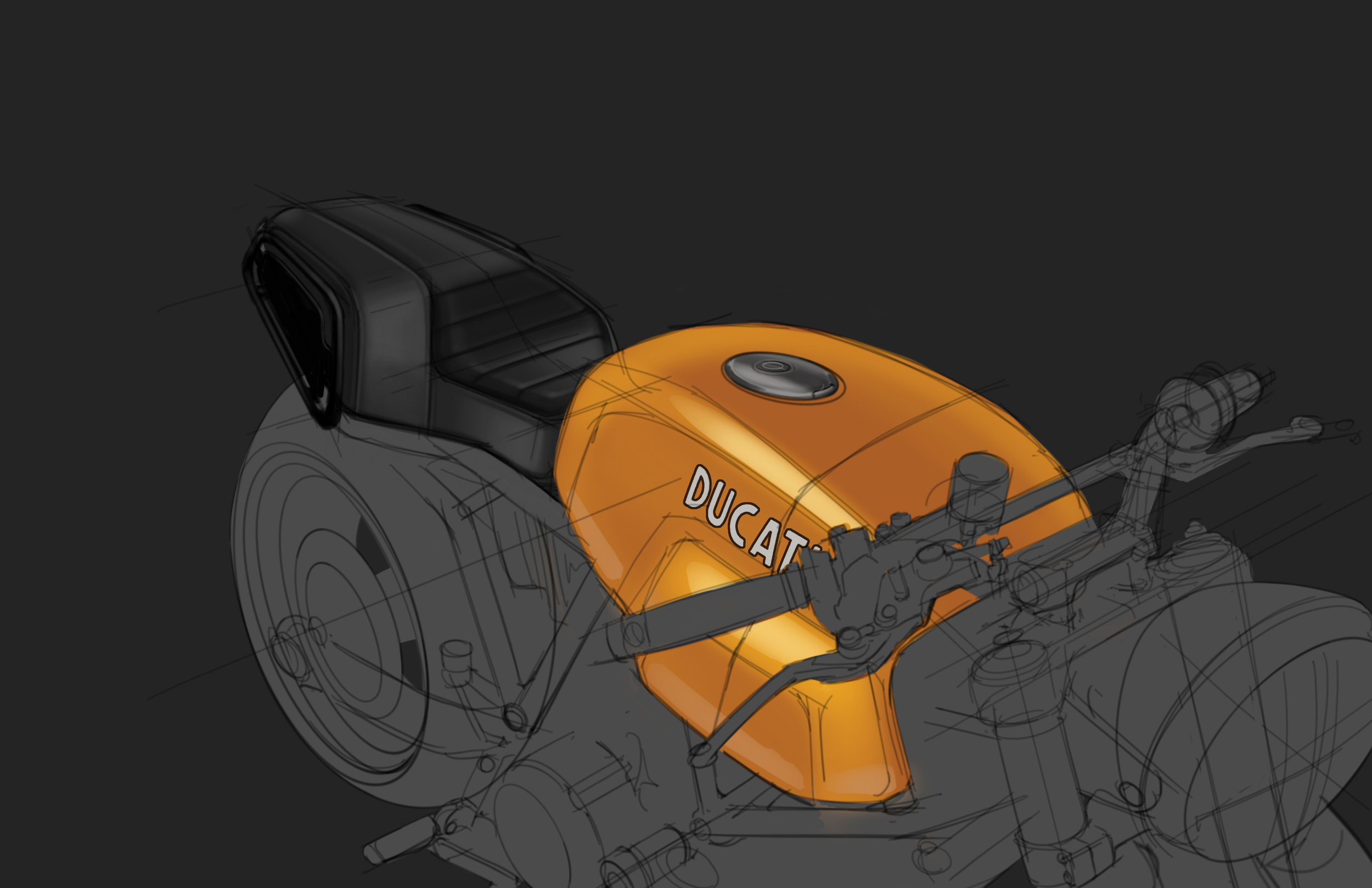
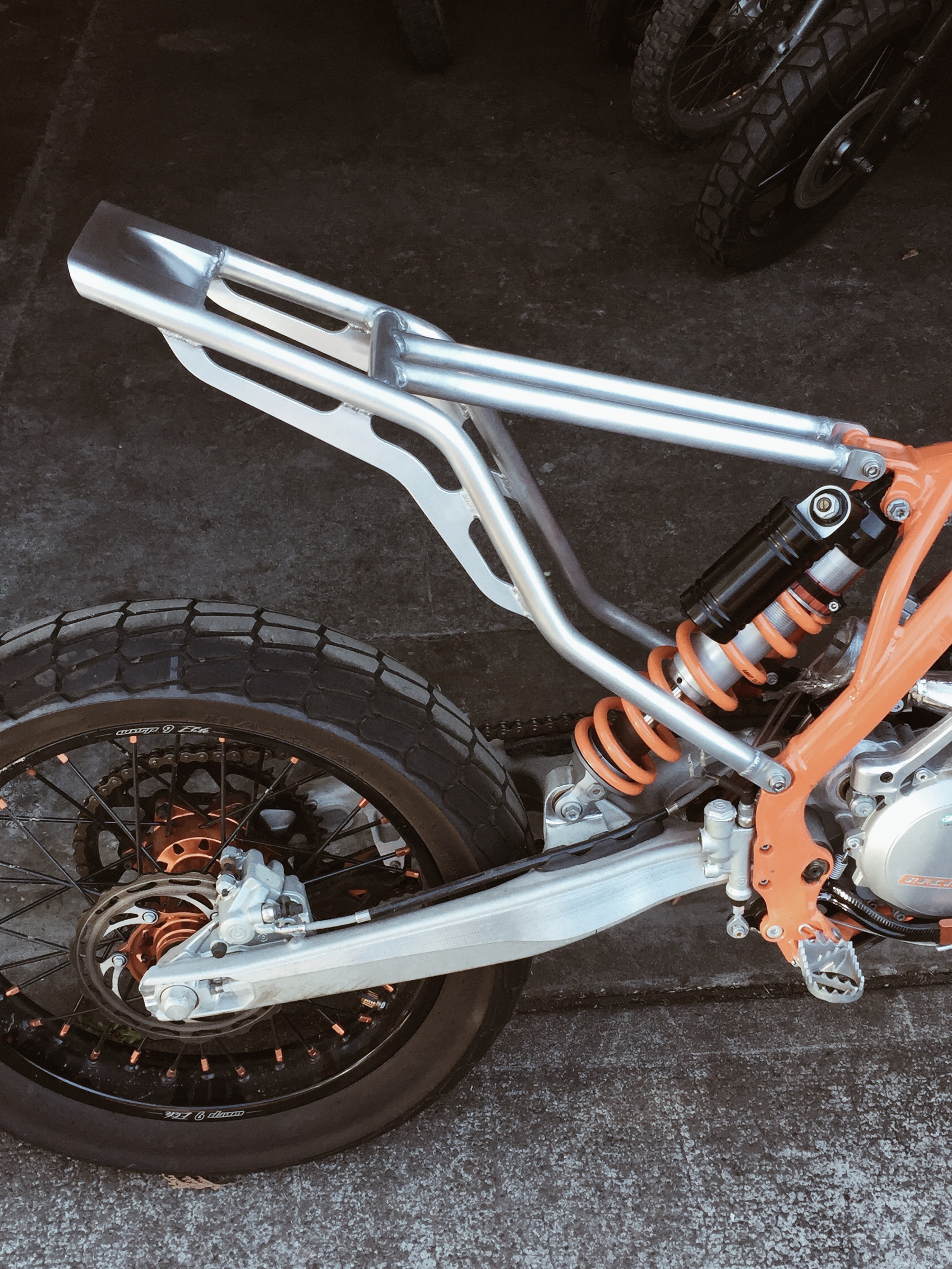
The 2nd to last concept was chosen. The idea was that it's shape would mimic the trapezoidal protrusions on the side of the SC tank. My goal was to reveal the subframe rails and also narrow up the seat width. These things have absurdly wide seats that look like they were grafted in from a Roadking. Here's a rendering of the complete bike with a few other mods we were tackling; Scrambler fenders and low rise MX bars.

Moto-Mucci_Custom_Ducati_Sport_Classic_Rendering.jpg

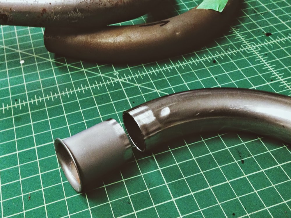
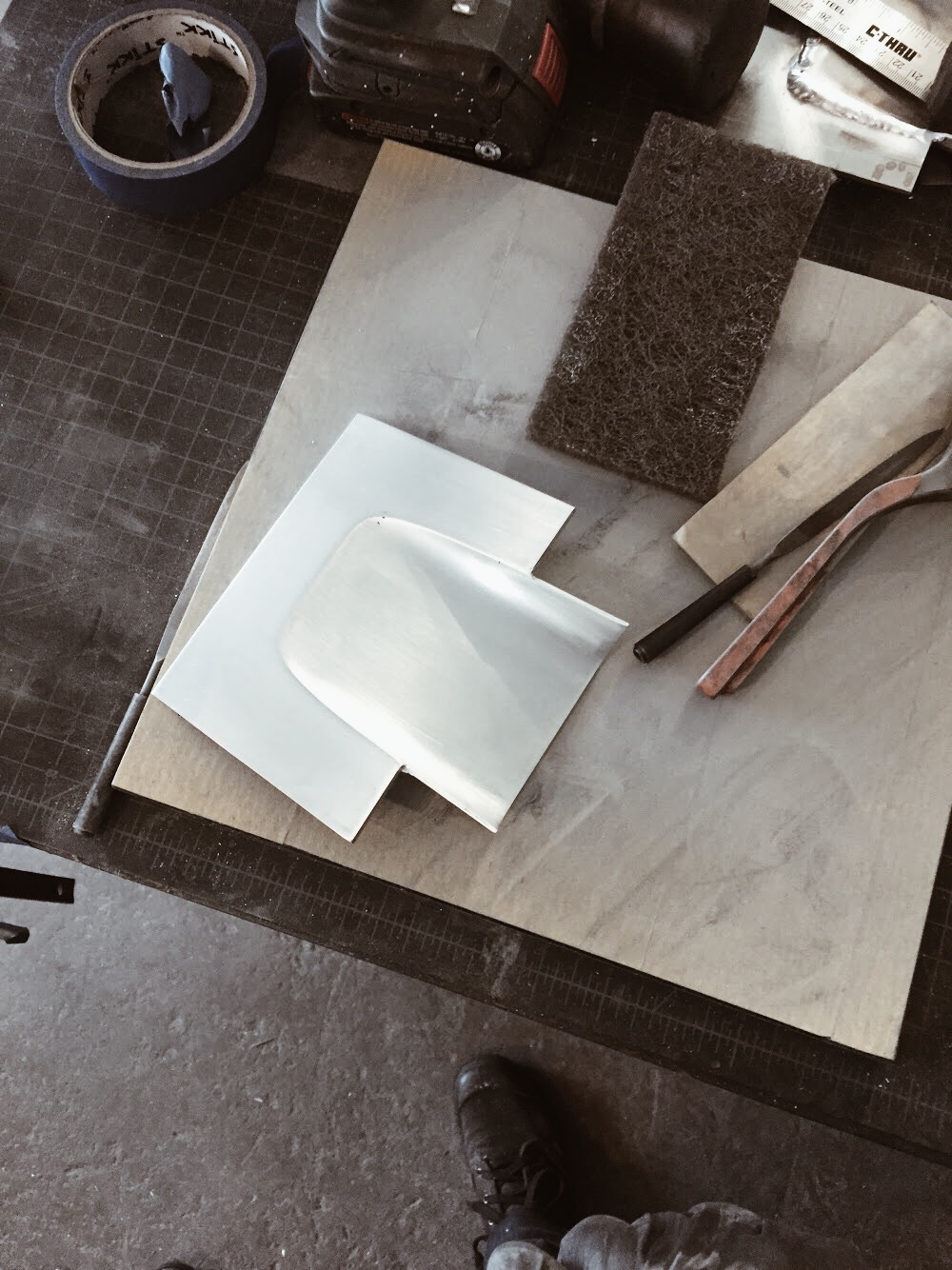
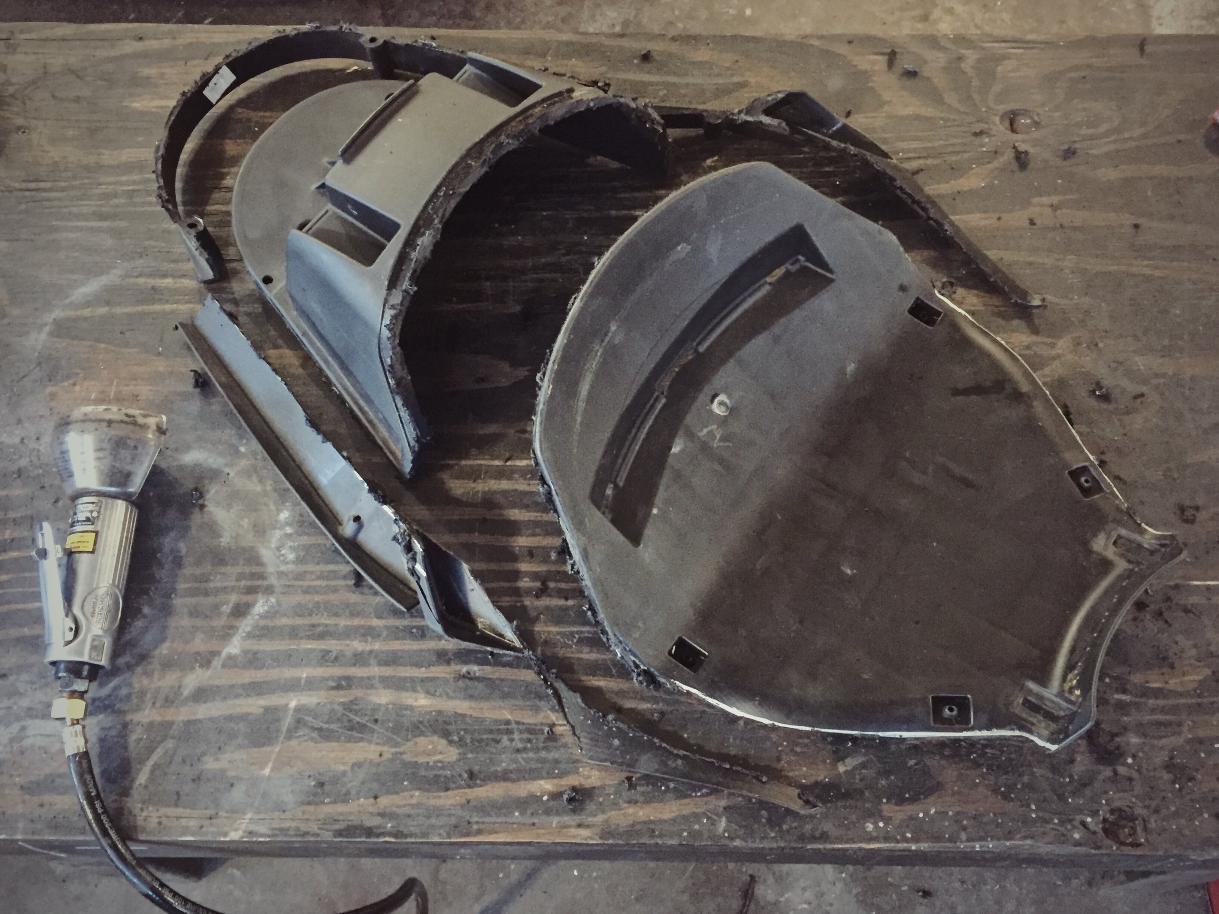
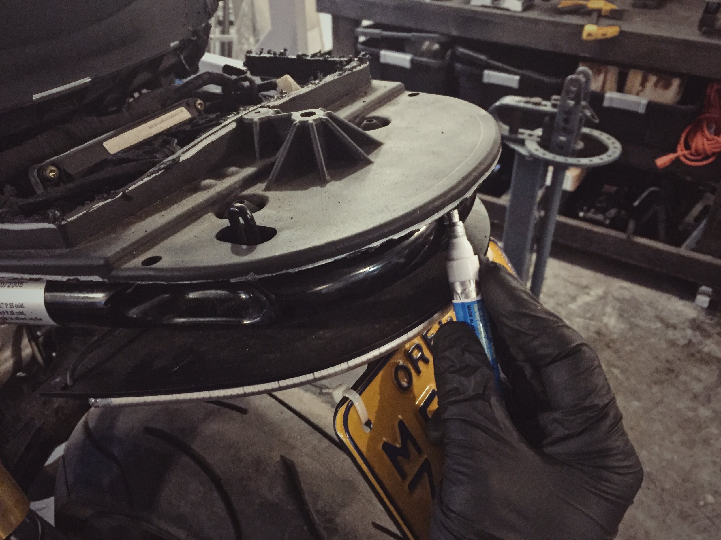
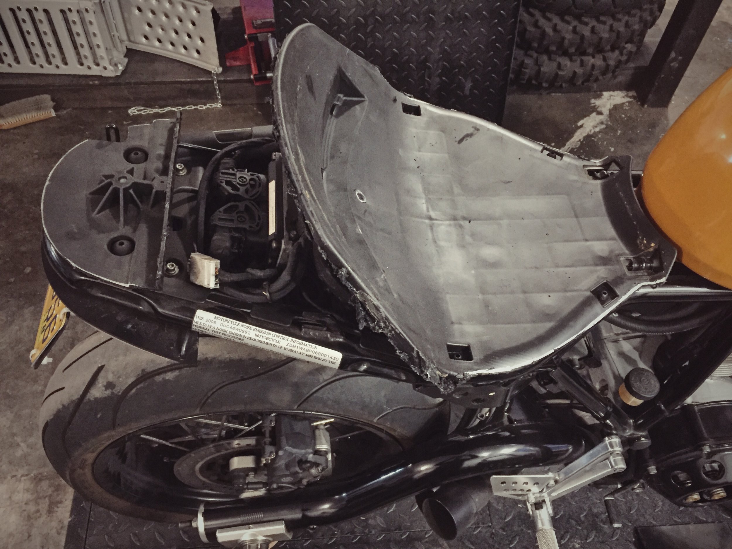
I was hoping I could get away with simply pulling off the cowl, cover and foam, laying down my own foam and reusing the stock seat pan. It turned out to not be that straight forward. The seat pan was wider and taller than the design called for so I began trimming and sectioning the plastic.

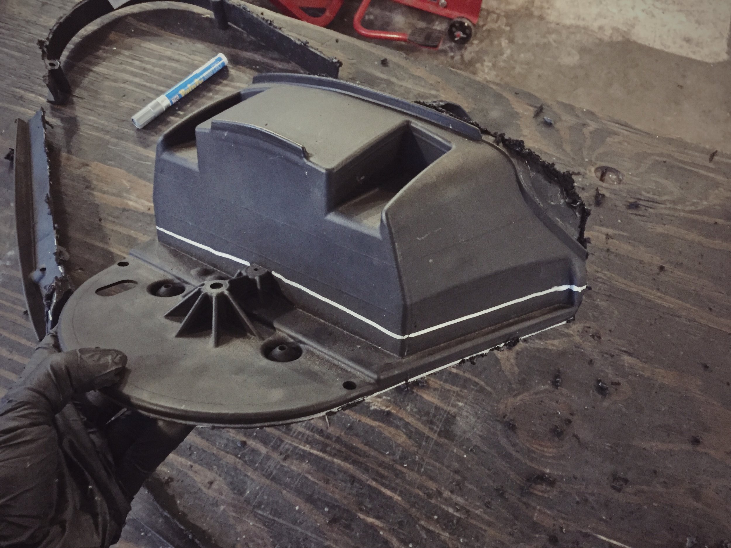
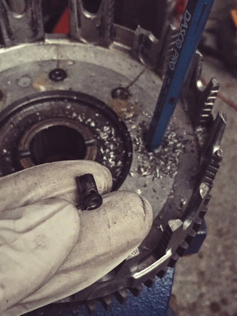
The goal soon became "try to at least save the mounting bits."

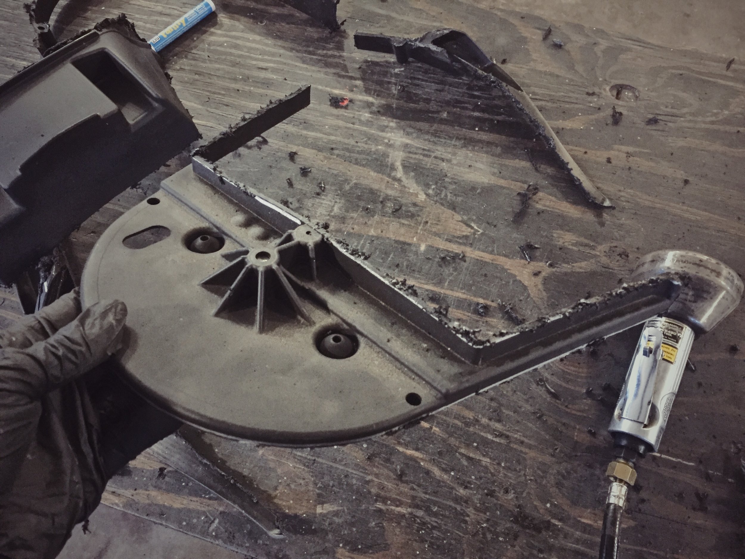
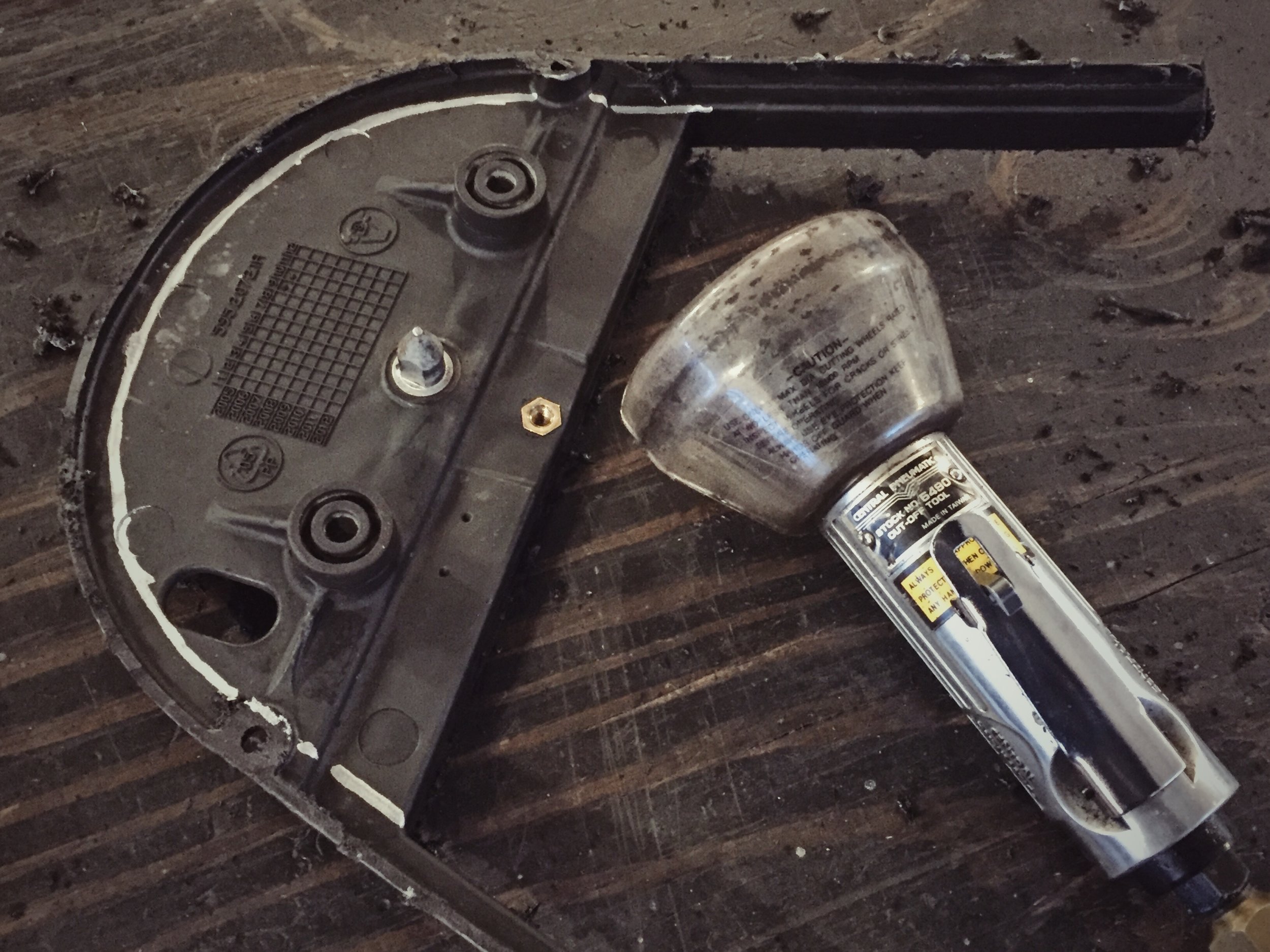
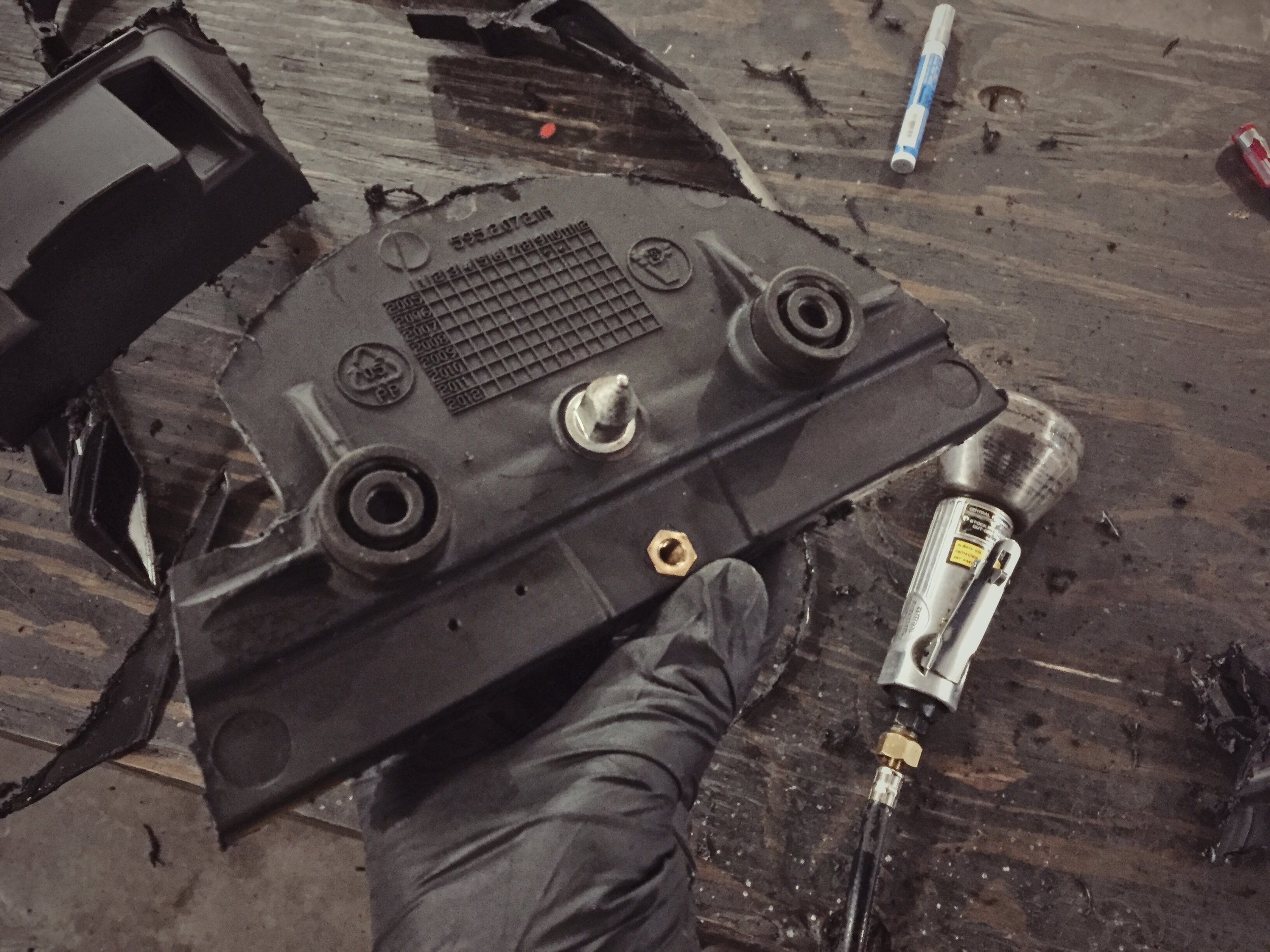
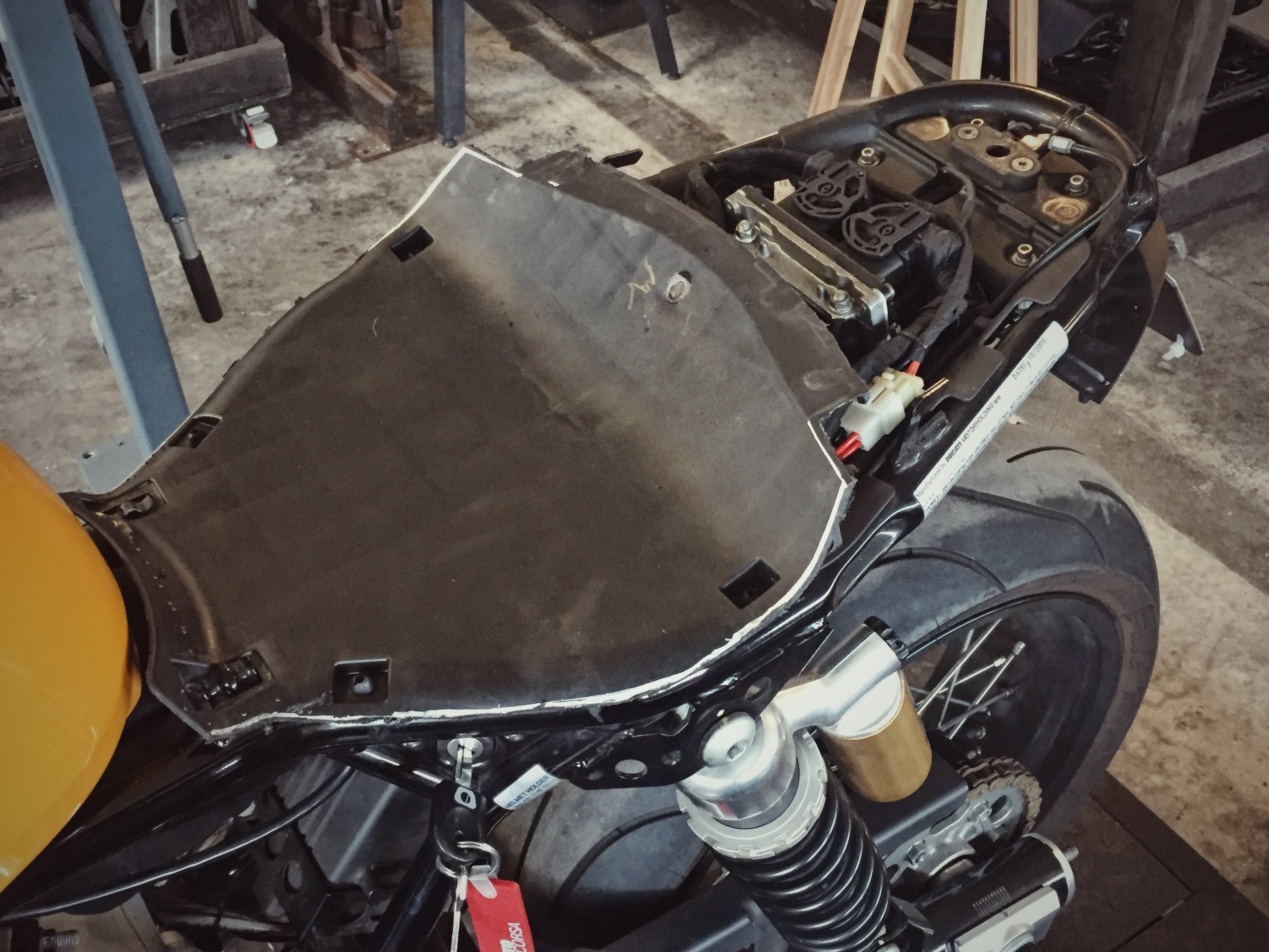
And the hackery has concluded. I was able to salvage all rubber mounting, the front hook system and the rear release latch. Next time - grafting the pieces back together.

DIY: Removing / Replacing Riveted Clutch Basket

A quick how-to on removing and replacing your worn clutch basket. Baskets will usually get grooves worn into them over time from the plate tabs and eventually restrict movement, causing the clutch to drag. The Husqvarna was doing just that so a replacement basket was purchased. 
Many baskets are riveted to the steel ring gear behind them. Here's how to remove the basket without damaging the gear.


Use a center punch to mark the center of each rivet then drill through with a small bit (1-2mm). Use some cutting paste to save your bits from all the drilling you're about to do. I use "Coolcut" from Walter.
This clutch has a sleeve bearing. Make sure not to touch the inner bearing surface. It'll likely have metal shavings on it and you don't want to scratch it. I put my gear under running water and then blew it out with compressed air after separating the 2. If yours has a ballbearing tape it off before drilling.  


Step up to a 4-5mm bit and drill a slightly larger hole. Make sure your bit is narrower than the holes in the gear so you don't bore out the steel. (check out the grooves in the basket and the broken prong.)


Here's what it'll look like from the backside. What you've done is weakened the structural integrity of the rivets and given yourself a guide hole for the next step.


Now choose a bit that has the same diameter as the rivet head.


Drill down until you start hitting the aluminum of the basket. You can feel the different between the steel rivet and aluminum basket. What you need to do is drill away the rivet's head. Eating into the basket a bit is fine since it's trash. 


Next find a punch that's larger than your pilot hole but smaller than the hole in the steel gear. Punch out the remaining rivet. It should pop right out with a few whacks. If not then you probably haven't drilled away the rivet head entirely. 


Here's what's left of the rivet. Repeat, repeat, repeat.


Off it goes. Remember, wash the shavings off with running water and compressed air before applying assembly grease to the bearing surface.


Many aftermarket clutch baskets are reattached with bolts instead of rivets. I scored this lightweight Surflex billet clutch basket off eBay. (One of the few company's that makes one for the TE) It came with steel rivets instead of bolts. To reapply the rivets you'll need a rivet hammer (pneumatic) and bucking bar. Here's a video on how to use a rivet hammer. Otherwise you'll need to find a shop that has one. 
I happened to have everything from a previous project with Snap-on. The steel rivets require a higher PSI to squash. I had my gun setup at 120psi in order to get them to deform enough (1.5x the size of it's start diameter). Use several small c-clamps to hold the 2 pieces together while riveting so there's no play in the fitment. Sorry, I installed the new basket on a different day and forgot to take photos.

DIY - E28 Wooden Shift Knob Mod

Personally, I love the ergonomics of the E28's "dogbone" shift knob much better then the popular MTech knob. So much so that I wore through the leather wrap on mine. What the wore out leather revealed was that the knob was made of wood. Solid wood. It'd be a shame to just discard such a thing...


Badge is held on my double sided tape.

Clean up and sand to 600 grit.


After 16 coats of semi-gloss lacquer.

Re-apply badge with 3M double sided automotive badge tape.

PROJECT DREAMONE50: How To Replicate an Exhaust 101

Turns out finding a clean set of headers for one of the first motorcycles Honda brought to the US is nearly impossible. Lucky for me the Honda CA95 exhaust may be the easiest system to replicate. The radii of the bends differ slightly from the left to right cylinder but otherwise they're just one bend then straight back. The only aftermarket systems out there are from Taiwan and are not mandrel bent. This means the pipes have a crushed inner radius and are oval through the bend zone. I bought a set of these to check them out. They were indeed total shit. Here's a quick tutorial on how I made a fresh set.
The first hurdle I had was sourcing the correct mandrel U-bend sections. Pipe bends are measured by their center line radius, or CLR. The pipes on this bike are only 1.25"OD so they're difficult to find especially in specific radii. My stock bend measurements were around 4.00" CLR for the left cylinder and 3.75" CLR for the right. I found U-Bends in the 3.75" measurement at www.mandrel-bends.com but could not find 4" anywhere. So I bought 2 of the 3.75" to see if I could make it work. Which I did. I won't leave you hanging.

1. Chopped out the bend section of the stock pipes, leaving at least a couple inches of straight on either end.
2. Set up the above jig to map out the angle coming from before and after the radius. 


3. Fit the new bend into the jig aligning it against one of it's straight sections. In this case the upper straight. Mark where the lower portion of the bend touches the jig/wood and mark your cut at 90 degrees to the jig.

4. Chop it. Above is showing what the new setup will look like pre-weld.
5. Put the stock pipe with header flange back into the jig and mark where the flange ends (I marked it on the upper piece of wood.)


6. Chop the header fittings from the old pipes (or buy / make new ones if you can. I didn't have anything that could recreate this style flange.)
7. Chop the new pipe down (engine side) per your measurements then tack the old flange onto the new pipe. It's always best to tack weld things together until you're sure everything fits before fully welding. This lets you snap the pieces apart easily should something not line up.


8. I installed the header with tacked on flange to the engine then hovered the straight section in there to make sure the exit angle was correct. I then tacked the straight sections on exactly where I wanted them. Don't forget to match pipe exit height from the rear of the bike. 


Here they are all tacked together. I probably used 4 tacks per intersection. You want enough tacks for them to hold their own weight. 
9. Time to weld! Make sure you have 3-4 tacks evenly spaced around the pipe before welding. This will prevent the pipes from warping away from eachother due to the heat of welding. Throw them back on afterwards to check your work. If they moved you probably either didn't have enough tacks and/or used too much heat.


10. Time to smooth the welds. You can use a pretty coarse file to knock the welds down flat to begin with then just step to a medium and fine grit. Your goal is to get all the scratches from the previous grit out. Take it slow, it's time consuming. You don't want to dip into the new pipe otherwise you'll create a valley in that area that will be visible after polishing. Always hit it at a 45 degree angle to avoid deeply scoring the pipe with the edge of the file. After hitting it with a fine grit file I bring the pipe to the bench grinder where I go over it with a medium and fine grit metal finishing wheel. They're basically Scotch-Brite pads in wheel form. 3M and Norton make good ones. 


That's all for now. I still have some hours of filing and polishing to do to these welds. After that I'll start making some rear brackets and mounting for the bafles. 

PROJECT SR250: Making an Assembly Table

After attempting to roughly assemble the SR250 on the floor of my garage, and then again on a standing work bench, I quickly realized my need for an assembly table. Companies like Harbor Freight offer cheap hydraulic options, like this, but it's still $420 and in all reality, I'm probably not going to need the hydraulic function very often.

Instead, I decided to build my own and came across this DIY. I ran out to Home Depot and picked up the lumber, screws, and some eyelet tie-down hooks for about $70. I then grabbed this $20 wheel chuck from HF.

Cutting and assembly probably took a total of 4 hours.


And there's the finished product. Not bad for $90. You can see the tie-down hooks inserted into the 4x4 legs for strength. The $20 wheel chuck works fine with a couple tie downs, just don't expect it to hold your bike up on it's own. HF does have one that will do just that for a higher price.

The table stands 30" tall and it's a great height for both standing and sitting work. Now that I had an adequate surface, I started roughly assembling the SR250. I'm doing this to check clearances, plan out a spot for the battery box, and start planning out the new wiring harness.

After that, it'll get torn back down and everything will be getting it's final finishes.